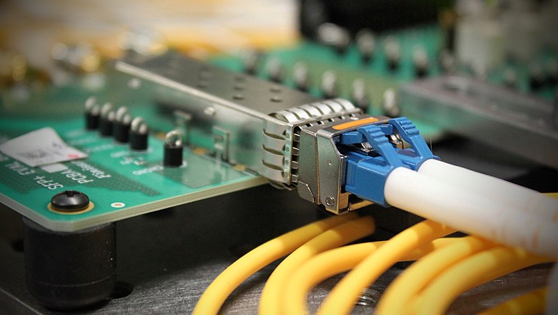
The optical transceiver module with digital diagnosis function mainly includes four parts: control module, transmitter module, receiver module, and optical module interface. Control module The control module is the monitoring and control center of the entire optical transceiver module. It is composed of functional chips or microcontrollers and peripheral devices. It is responsible for data acquisition, processing and storage in the process of digital diagnosis, and monitoring and control of various signals of the optical module. The control module provides the bus interface. It is the data transmission channel of the entire optical transceiver module. According to a protocol, the storage unit has two parts. It is used to store some basic general information of the optical module, such as company information, production date, serial number, module type, wavelength and transmission length. It is used to store the digital measurement results of analog parameters, calibration parameters, warning and alarm closing values and flag bits, control flag bits, status flag bits, etc. The modules of optical module manufacturers strictly follow the following design standards.
The main function of the optical transmitter module in the optical transmission process is to convert the electrical pulse signal into an optical pulse signal, the input is an electrical signal, and the output is an optical signal. As shown in Figure 1, the transmitter module is mainly composed of a laser driver, a laser and a backlight diode. The main function of the receiving module is to convert the weak optical pulse signal that is attenuated and deformed after being transmitted by the optical fiber cable into an electrical pulse signal through photoelectric conversion, and give sufficient amplification, equalization and timing regeneration to restore it to a standard digital pulse signal. The schematic diagram of the optical receiving module is shown in Figure 1. The limiting amplifier consists of three parts: power amplifier, equalization filter, and regenerator. The receiving component is composed of four parts: photodetector, preamplifier, AGC circuit, and high-voltage converter.
The photodetector is the core device of the digital optical receiver. It converts the optical pulse signal into an electrical pulse signal through photoelectric conversion. The commonly used are mainly photodiodes and avalanche photodiodes. The optical signal enters the photodiode from the optical interface and is converted into a weak current. The current is converted into a voltage through a preamplifier and amplified to an appropriate level in one stage.
The overall technical indicators to be achieved by the optical transceiver module are used for short-distance high-speed optical fiber communication working rate 1. Standard structures such as electrical, optical, and mechanical interfaces that comply with multi-source protocols are hot-swappable and meet the timing specifications. Provides intelligent digital diagnostic interface functions and compatible protocols. Compliant with two-wire communication protocol with master and slave communication mode capable of self-detection rate. The digital resistance is automatically compensated to meet the stable average optical power and extinction ratio of the output. Meet the monitoring indicators of five analog parameters.
The paper was written by engineers at QSFPTEK. If you have any questions about QSFPTEK’s optical transceiver products, please contact us.
